|
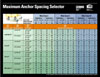
Design of the Anchor Chart
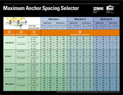
The chart, presented on a durable, laminated card, indicates the
maximum spacing for desired anchors for use in different wind zones
and for different home designs. Installers simply need to know the
HUD wind zone and the dimensions of a few features of the home,
including section width, main I-beam spacing, and pier height to
locate the recommended maximum anchor spacing. Spacing values vary
by anchor length and home type (single or double section). The testing
confirmed the view that stabilizer plates significantly improve
the performance of the anchoring system, so the chart also lists
recommended plate sizes for each anchor.
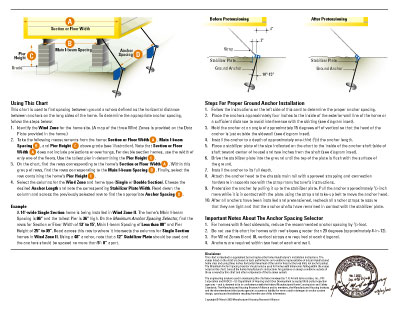
Instructions on using the chart are found on the back of the card
along with an example, leaving little room for misinterpretation.
Also included are guidelines for the installation process.
The chart is meant to augment the manufacturer's installation
instructions that often are rather detailed and may run to many
pages of tables, charts and explanatory text. Not surprisingly,
the values on the chart may not match the values contained in the
manufacturer's instructions. The chart embodies one set of engineering
assumptions arrived at through careful review by the Committee and
represent a consensus view. For example, only Class 4 soil is assumed
in the computations supporting the chart. Individual manufacturers
may use different assumptions and tailor their instructions to company-specific
designs.
The authors of the chart recognized that a simplified procedure
could not cover every design variation. Rather, the intent was to
cover designs that represent the vast majority of new home construction.
For example, the chart includes values for homes with an industry-standard
roof pitch of 20 degrees or less, and pier heights up to four feet.
The anchor spacing selector does not cover homes that fall outside
of these boundaries.
In a few instances, the engineering analysis suggested
anchor spacing values that were less than the anchor length. These
values were omitted from the chart. The SBRA committee overseeing
the project recognized that at such close distances between anchors
there would be overlapping "cones of influence" where
the same soil is being counted on to hold more than one anchor.
The Committee acknowledged that the importance of the cone of influence
to the performance of the anchoring system is not well understood
and is an area for subsequent research. Until further study, installers
are cautioned to choose another anchor size for these combinations
of design conditions or to use professional assistance to engineer
a site-specific solution.
The engineering analysis used in developing this
chart was reviewed by T.R. Arnold & Associates, Inc., PFS Corporation
and RADCO - US Department of Housing and Urban Development accepted
third-party inspection agencies - and is deemed to be in conformance
with the federal Manufactured Home Construction and Safety Standards.
|