|
Anchoring Systems
As part of a larger effort to improve the performance of foundation
systems, the Systems Building Research Alliance coordinated the
development of guidelines for anchor system design and installation.
The project was, in part, an outgrowth of work, initiated by the
Manufactured Housing Institute Technical Activities Committee (TAC)
Alternative Task Force with a similar goal. The results of the combined
SBRA and TAC Committee-directed effort are described in the report.
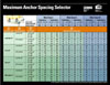
The goal of the project was the development of an easy-to-use instruction
card that will take the guesswork out of designing the anchor installation.
The chart was the culmination of a
three-step effort as follows:
- Field testing of anchors in soils typical
of manufactured housing sites. The rigorous field-testing program
gauged the strength of various anchor and stabilizer plate combinations.
Representatives of Froehling & Robertson, an independent,
nationally recognized geotechnical engineering firm, monitored
the tests. F&R also took soil sample, conducted laboratory
analysis of the samples and analyzed the test data..
- The raw data provided by F&R were reviewed
by Edward Salsbury, PE and converted into design specifications
for various combinations of design features including, home widths,
pier heights, I-beam spacings, wind zones and anchor/stabilizer
plate pairings.
- The engineering analysis results were then
condensed into the tabular form displayed on the anchor chart.
Instructions for using the chart and basic steps for proper ground
installation are printed on the back of the chart
Field-testing
The field-testing employed a test caravan that spent a week on the
road stopping at sites across the Southeast chosen for their relatively
poor soils. Most of the tests took place in sand or sand and silt
soils, which typically do not hold anchors as well as soils with
higher clay content. The poor soils were chosen to represent a condition
that might occur at a manufactured home site, assuring that the
guidelines developed from the test results could be used anywhere
in the nation and in the absence of detailed soil measurements would
provide a margin of safety.
|
|
|
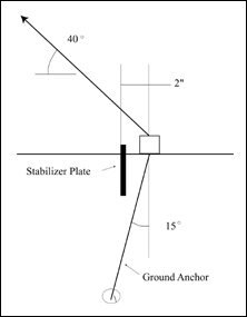
Figure 3: Ground Anchor Installation
|
At each site, the testing crew installed various
anchor and stabilizer plate combinations and with the help of a
winch and dynamometer, measured their holding power. In all, one
hundred and sixty-two anchors - including almost all of the anchors
in common use - were tested to determine their safe load resistance,
or pull-out value, in various soils. Products tested ranged in size
from 30" anchors with 12" stabilizer plates, to 60"
anchors with 17" stabilizer plates. The criteria for anchor
failure were three inches horizontal movement or two inches of vertical
movement of the anchor head, not anchor pullout.
A second set of field tests were conducted to fill in some of the
data gaps identified subsequent to the first set of tests. These
included testing 30" and 36" anchors with 17" stabilizer
plates. The second group of tests was conducted in Baxley, GA and
Edgefield, SC.
Some of the preliminary findings were rather surprising. For example,
the results suggest that a commonly used measure of the holding
capacity of soil - the torque test - is not a particularly helpful
tool in designing the anchor system. The torque testing results,
or the measure of the force it takes to put an anchor in the ground,
correlated poorly with the force required to pull the anchor out
of the ground. The original plan was to produce guidelines for installing
anchors in soils of both known and unknown holding capacity. The
testing results, however, cast doubt on the ability of the installer
to accurately measure the holding capacity of the soil with the
tools typically available at the building site. Among the other
preliminary conclusions from the testing were that every installation
should include pretensioning of the anchor strap and stabilizer
plates should be used for all types of anchors.
The testing also shed light on the actual working
load of the anchors, nominally assumed to be 3,150 lbs. The tests
yielded the following actual working loads for the various anchor
length/stabilizer plate/wind zone combinations
Table 1 Actual Working Loads (lbs.) for Anchor
and Stabilizer Plates Tested
|
WIND ZONE I
|
WIND ZONE II
|
WIND ZONE III
|
| 30" or 36" anchor
with 12" plate |
48" or 60" anchor
with 17" plate |
48" anchor with 12"
plate |
48" or 60" anchor
with 17" plate |
48" anchor with 12"
plate |
48" or 60" anchor
with 17" plate |
| 2,000 lbs. |
3,150 lbs. |
2,500 lbs. |
3,150 lbs. |
2,500 lbs. |
3,150 lbs. |
Engineering analysis
The field test results were translated into anchor spacing recommendations
by applying standard engineering procedures. The spacing estimates
were developed for combinations of wind zone, home width and type
(single and double section), I-beam spacing and pier height. Values
were derived for common anchor sizes (30", 36", 48"
and 60") with either 12" or 17" stabilizer plates.
Representative values from these tables were used to construct the
final chart.
|